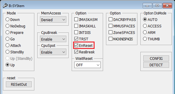
The debugger uses the JTAG RESET pin (nSRST) which is connected to the debug connector (pin15 at the 20-pin debug connector, pin 10 on the 10-pin MIPI connector). The SYStem.Up command resets the target via the reset line only if SYStem.Option.EnReset is set to ON. Please check if this option is enabled in the SYStem window (menu CPU > System Settings...):

Please also check if the reset line of the debugger is properly connected to the chip reset (like the reset button).
It may be also possible that the reset line, that is pulled low during SYStem.Up per default, does not reset the entire SoC. A SYStem.Up cannot in this case reset the device completely. The processor will then not start from a reset context with the device, which might cause the boot issues. The reset button and the nSRST pin might also be connected to different points on the board, so check the board schematics. Sometimes, there is a reset logic in between that treats the reset button and the nSRST differently. So also explore the option to disconnect the nSRST and reroute it to the reset button with a wire, to achieve the same reset the reset button does.
Check for custom reset register
Please also check if a SoC specific reset mechanism via a register interface is available (i.e., a core reset be triggered by writing to the proper register). If yes, then this might be used together with the command SYStem.Option.RESetRegister.
Develop custom reset script
If the reset cannot be done by a single register, e.g. if multiple custom registers are written, the reset sequence should be put in a PRACTICE script. For example, the script could access the reset register via the AHB/AXI in SYStem.Mode Prepare. Then, having done the reset, the debugger could connect with SYStem.Mode Attach. Attach does not ensure the CPU is at the reset vector, so to keep the CPU at the reset vector, try to put an endless loop at the reset vector before releasing the CPU from reset again. This can also be done in "Prepare" mode, if the CPU memory is accessible via AHB/AXI. In this case use the Data.Assemble command as shown in the template script below:
// This example outlines a rough scheme how a CPU could be reset via a custom
// register sequence and held at the reset location if the CPU starts from a
// writeable RAM location, e.g. SRAM
SYStem.CPU < cpu >
SYStem.Mode.Prepare
Data.Set [EAHB | EAXI]:<register1> % < value > // Bring core(s) into reset
Data.Set ... // Additional settings, e.g. start address after reset
Data.Assemble [EAHB | EAXI]:< start_addr > b $-0x0 // Assemble endless loop
Data.Set [EAHB | EAXI]:< register_n > % < value > // Release cores(s) from reset
Data.Set ...
CORE.ASSIGN 1. 2. 3. ... // Assign as many cores as released
SYStem.Mode Attach // Attach to running cores
Break.direct
Moreover, the following template script allows to catch the CPU at the reset vector (Armv8 only):
// This example outlines a rough scheme how a CPU could be reset via a custom
// register sequence and caught at the reset vector with a reset catch mechanism.
// This might be useful if the core starts from a location that cannot be
// modified, e.g. ROM, so that an endless loop _cannot_ be assembled
SYStem.CPU < cpu >
CORE.ASSIGN 1. 2. 3. ... // Assign as many cores as released
SYStem.Mode Prepare
Data.Set [EAHB | EAXI]:< register1 > % < value > // Bring core(s) into reset
Data.Set ... // Additional settings, e.g. start address after reset
// Enable reset catch, in this example for Armv8. '/CORE' is not needed for single core setups
Data.Set e:(COREBASE()+0x24) %Long 0x2 /CORE 1
Data.Set e:(COREBASE()+0x24) %Long 0x2 /CORE 2
...
Data.Set e:(COREBASE()+0x24) %Long 0x2 /CORE n
Data.Set [EAHB | EAXI]:<register_n> % <value> // Release cores(s) from reset
Data.Set ...
SYStem.Mode.Attach // Attach to stopped cores

Comments (2)
Hello, To ensure a proper support, please open a new ticket: "https://support.lauterbach.com/new-ticket" provide more details about the issue (target, scripts used, etc.), include relevant screenshots, and generate a system information report about your TRACE32 configuration by selecting the TRACE32 menu 'Help' > 'Support' > 'System Information...', click 'Save to File' and send the resulting text file as an attachment to your e-mail.